Thursday, December 19, 2013

An outstanding fluid simulation researcher

I am utterly impressed by Ryoichi Ando.
http://vacation.aid.design.kyushu-u.ac.jp/~and/

Currently a third year PhD student and has already produced some outstanding work. He is the guy behind smoke3d (code.google.com/p/smoke3d), 2dsmoke and other open source fluid code out there.

He invented flip3d, sheet preserving fluids (http://vacation.aid.design.kyushu-u.ac.jp/~and/sheetflip/index.html ) as well as highly adaptive liquid simulation recently published at SIGGRAPH 2013 (http://pub.ist.ac.at/group_wojtan/projects/2013_Ando_HALSoTM/index.html)

Whats realy good about him is that he has kept all of his work open sourced with a permissive BSD license. Really awesome work. 

Tuesday, December 3, 2013

A free online book on fundamentals of ray tracing

Although this book does not cover acceleration structures, it does give a fair amount of detail for beginners. Thought of putting a blog post in for this invaluable free resource. Here are the table of contents at a glance

Sunday, July 21, 2013

Mitsuba Renderer: Loading PLY model files

In this tutorial, we will look at how to load the PLY dataset. Such datasets are quite common in graphics research and most rendering papers present their outputs for these datasets. These can be downloaded from the Stanford 3D scanning repository. I will assume that you have the required dragon.ply dataset downloaded and placed in the same location where your scene XML is.

Loading a PLY dataset is as simple as adding the following scene element.

< shape type="ply" >
   < string name="filename" value="dragon.ply"/ >
   < bsdf type="roughdielectric" >
      < ! -- Tweak the roughness parameter of the material -- >
      < float name="alpha" value="0.01" / >
    < / bsdf >
< / shape >

As can be seen it is very simple. Just change the shape's type to ply and then add the shape's bsdf. Here we have chosen a rough dielectric material to give the dragon a glass appearance. You can change the roughness value which controls how clear the glass is.

I rendered the glass dragon using path tracing, photon mapping, path space MLT (PSMLT), primary sample space MLT (PSSMLT) and energy redistribution path tracing (ERPT). The results are as follows

Path tracing

Energy redistribution path tracing (ERPT) 

Primary sample space MLT (PSSMLT)
Path space MLT (PSMLT)
Photon mapping
As in earlier tutorial, the full scene file may be downloaded from here: https://www.dropbox.com/s/h93wuwmbhkz8ozd/loadPly.xml

Thursday, July 18, 2013

Mitsuba Renderer: Rendering spheres with plastic material and different integrators


In the last tutorial, we looked at a fairly stardard Lambartian/Diffuse material. We will now look at another material type which has specular highlights. This material type is called plastic in Mitsuba. We will render a large checkered plane with three spheres having red, green and blue plastic material so lets get started.

We define our sphere shape as in the first tutorial however the only difference is in the bsdf which has a different color for each sphere. The three spheres are defined as follows:

< !-- Setup blue sphere -- >
< shape type="sphere" >
  < float name="radius" value="0.1"/ >
  < transform name="toWorld" >
    < translate x="0.0" y="0" z="0.0"/ >
  < / transform >
  < bsdf type="plastic" >
    < srgb name="diffuseReflectance" value="#0000ff"/ >
      < float name="intIOR" value="1.9"/ >
  < / bsdf >
< / shape >

< !-- Setup green sphere -- >  
< shape type="sphere" >
  < float name="radius" value="0.1"/ >
  < transform name="toWorld" >
    < translate x="-0.2" y="0" z="0"/ >
  < / transform >
  < bsdf type="plastic" >
    < srgb name="diffuseReflectance" value="#00ff00"/ >
    < float name="intIOR" value="1.9"/ >
  < / bsdf >
< / shape >

< !-- Setup red sphere -- >
< shape type="sphere" >
  < float name="radius" value="0.1"/ >
  < transform name="toWorld" >
    < translate x="0.2" y="0" z="0"/ >
  < / transform >
  < bsdf type="plastic" >
    < srgb name="diffuseReflectance" value="#ff0000"/ >
    < float name="intIOR" value="1.9"/ >
  < / bsdf >
< / shape >

Lets look at one of the sphere's brdf properties in detail. The type for the bsdf in this case is plastic. The diffuseReflectance is the color of the material. If you look at Mitsuba documentation, this property is defined as a spectrum type. There are many ways to define a spectrum. We define it here as a hexadecimal srgb value. We could also define colors in rgb space (for e.g. blue with value="0.0,0.0,1.0") which would give the same output. The last parameter is the interior index of refraction. The rest of the scene elements are the same as in the previous checkered plane tutorial.

One neat feature of the Mistuba front end mtsgui is that it allows us to change the integrator type in real-time using the render settings options (the gear icon in the GUI) as shown below.

Render settings in mtsgui
There are 14 integrators to choose from. I have rendered current scene in all of the available integrators and the output results and timings are written for each integrator in the image caption. Note that these timings were calculated on my laptop with an AMD Radeon (TM) HD 6630M GPU hardware and these will likely differ on your machine. For some of the integrators like adjoint path tracer, path space MLT, progressive photon mapping and stochastic photon mapping, the scene could not converge. Here are all of the rendering for reference.

Adjoint path tracer [3.5970 secs @ 640x480]
Bidirectional path tracing [22.8360 secs @ 640x480]

Ambient occlusion [2.2860 secs @ 640x480]

Energy redistribution path tracing [1.5050 m @ 640x480]
Direct illumination [4.5020 secs @ 640x480]
Path space MLT [N/A @ 640x480]
Path tracing [5.6050 secs @ 640x480]
Photon mapping [1.1671 m @ 640x480]
Primary space MLT [37.7090 secs @ 640x480]

Progressive photon mapping [>6.1809 m @ 640x480]
Stochastic progressive photon mapping [>1.1635 m @ 640x480]
Volume path tracing (simple) [5.2190 secs @ 640x480]
Volume path tracing (extended) [5.9080 secs @ 640x480]

Virtual point light [0.598 secs @ 640x480]
The full scene XML file may be downloaded from here: https://www.dropbox.com/s/d7z5rpc5sgwmcpe/checkeredPlaneRGB_spheres.xml 
You should play around with different render settings and integrators to see their effect on the rendering output. 

Wednesday, July 17, 2013

Mitsuba Renderer: A more complete example

In the last tutorial, we had looked at a very simple example usage of Mitsuba with only a single sphere primitive. We will now look at a more complete scene with the description of other entities like film, intgrator, bsdf etc. So lets get started.

In this scene, we will render a plane primitive with a checkered material. We will introduce the following new scene elements.
  1. integrator (for the rendering algorithm used)
  2. sensor (for the camera settings like fov) 
  3. film: a sub-entity of the sensor element (for the output image resolution and type) 
  4. sampler: a sub-entity of the sensor element (for the number of camera samples and the type of sampling distribution to be used.
  5. plane (for rendering of our plane shape)
  6. bsdf: a child entity of our plane shape (for the checkered material)
Integrator:
This element tells Mitsuba the type of rendering algorithm to be used for the scene. For the first few tutorials, we will stick with the path tracing algorithm (type="path") for the integrator element. For this scene, the integrator element is defined as follows:

  < !--Setup scene integrator -- >
  < integrator type="path" >

    < !-- Path trace with a max. path length of 5 -- >
    < integer name="maxDepth" value="5"/ >

  < / integrator >

Sensor:
This element is analogous to a camera object. For this scene, we will use a perspective camera (type="perspective"). Its sub-elements transform controls the camera's position and orientation, the focusDistance element controls the distance of the camera focal plane. The fov element controls the camera field of view.

Film:
This is the sub-element of the sensor element. Its main attribute type controls the format of the output (ldrfilm or hdrfilm). If hdrfilm type is used, the output format is EXR. The sub-elements width and height control the output image dimensions.

For this scene, the sensor element is defined as follows:

  < sensor type="perspective" >
    < transform name="toWorld" >
      < translate x="0" y="0" z="-1"/ >
    < / transform >

    < float name="focusDistance" value="1"/ >

    < float name="fov" value="45"/ >

    < film type="hdrfilm" >
      < integer name="width" value="640"/ >
      < integer name="height" value="480"/ >
    < / film >

    < sampler type="independent" >
      < integer name="sampleCount" value="32"/ >
    < / sampler >
  < / sensor >

Plane:
The plane shape is defined by the type ("rectangle"). The position, orientation and scale of plane is controlled through the transform sub-element. To orient the plane properly, we rotate then scale and finally translate it. The material is controlled by the bsdf sub-element. Here we have defined a diffuse material. The bsdf element has a texture sub-element which has a uv scale of 32 (that is the texture tiling amount), color0 and color1 are the two checker colors and filtertype controls the texture filtering scheme to be used. This can be 

  1. EWA (for EWA filtering which is the default filter type) 
  2. trilinear (for linear filtering)
  3. nearest (for nearest neighbor filtering)
For this scene, the shape element is defined as follows:

 < shape type="rectangle" >     
    < transform name="toWorld" >
      < rotate x="1" angle="-90"/ >
      < scale x="2" y="2" z="2"/ >
      < translate y="-0.1"/ >
    < / transform >
     
    < bsdf type="diffuse" >
      < texture type="checkerboard" name="reflectance" >
        < float name="uvscale" value="32"/ >
        < rgb name="color0" value="0,0,0"/ >
        < rgb name="color1" value="1,1,1"/ >
        < string name="filterType" value="EWA"/ >
      < / texture >
    < / bsdf >
  < / shape >

The entire scene description given above gives us the following output.
Output from the CheckeredPlane.xml scene
The scene file may be downloaded from here: https://www.dropbox.com/s/dtz7y9svuov7gxk/CheckeredPlane.xml 


Tuesday, July 16, 2013

Getting started with the Mitsuba Renderer

Mitsuba Renderer: An unbiased physically based  renderer written by Wenzel Jakobs who is a PhD student at Cornell. It is inspired and takes a lot of its design from the PBRT renderer of Matt Pharr. More details about this amazing renderer can be obtained from http://www.mitsuba-renderer.org/ I highly recommend this renderer to any student/researcher who is working on physically based rendering.

While the Mitsuba documentation is very well written, it lacks basic tutorials that teach the  user how the whole system works and this blog post will try to address these issues so lets get started.

If you have not done so then please download the latest binaries from the above mentioned website. As of this writing, the current version is 0.4.4. Extract the zip file to the root directory. In the binary package, there are a bunch of dlls (boost, OpenEXR, and others) and then there are a bunch of executables including the two main executables: mitsuba.exe (the main renderer) and the mtsgui (the Qt based GUI front end for the renderer). The mtsgui is the tool we will look at in this tutorial. This tool reads an XML based scene description written in any XML editor, parses it and renders the scene. When you run mtsgui, you get this window
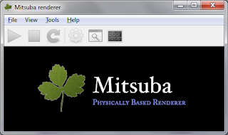
The mtsgui window (The graphical front end to Mitsuba) 

Hello World Mitsuba
Go ahead and create a new XML document in your favorite editor. I usually prefer MS Visual Studio as it provides a lot of neat tools. Add the following contents to it.

< ? xml version="1.0" encoding="utf-8"? >
< scene version="0.4.4" >
  < shape type="sphere" >
    < float name="radius" value="1"/ >
  < /shape >
< /scene >

This is a very simple scene that displays a simple unit sphere on screen. All other settings like camera position, fov, sphere's material, environment map are assigned their default values. Go ahead and save the XML as sphere.xml in a suitable place. Go to mtsgui and open this scene. When you open this scene, you will see that your sphere will occupy the entire rendering window as shown below.

The sphere.xml scene rendered in mtsgui
This is the preview render of our scene. We can use the left mouse button to rotate the camera and use the up/down arrow keys to zoom in/out etc. Single left mouse click on our sphere selects it while double clicking on it zooms out the camera to properly display the sphere (similar to zoom extents of 3DSMax). Go ahead and double click on the sphere. This will give us the following output in mtsgui window.
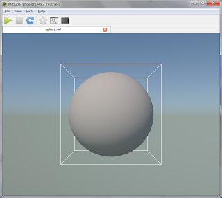
Sphere after double clicking in mtsgui window
Now press the play button which will render our scene using path tracing as shown below.
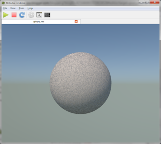
Our sphere object path traced
This is a simple getting  started tutorial for Mitsuba. For more details about the mtsgui interface options, go through this video by Wenzel Jakob http://vimeo.com/13480342. I will follow up with more tutorials as and when time permits. You can download the final sphere.xml from here https://www.dropbox.com/s/i0gv68zw9211yo4/sphere.xml

Happy path tracing.

Popular Posts

Copyright (C) 2011 - Movania Muhammad Mobeen. Awesome Inc. theme. Powered by Blogger.